

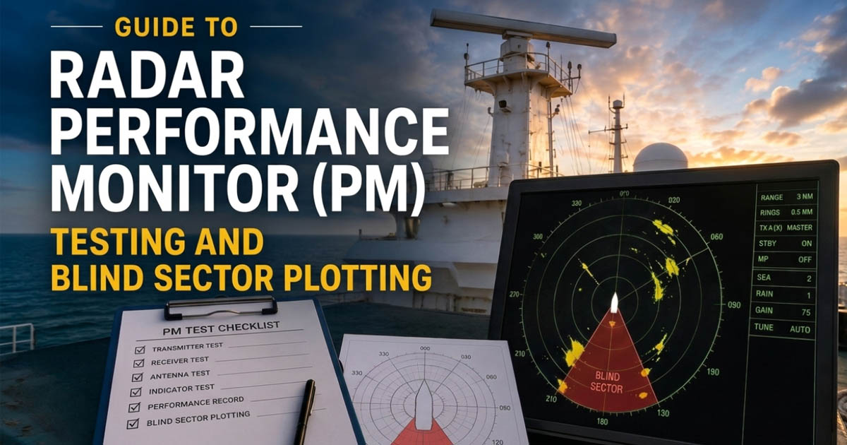
A radar performance monitor provides a means of checking transmitter and receiver performance against a calibrated standard established during installation or commissioning. Manufacturers may provide specific procedures and intervals for conducting these checks.
IMO Resolution MSC.192(79), section 5.7.3, requires radar equipment to provide a means of determining a significant drop in system performance relative to a calibrated standard established at installation. SOLAS Chapter V, Regulation 19 establishes the applicable carriage requirements for radar equipment.
This guide covers PM testing, magnetron degradation signs, and blind sector plotting.
Why Radar Performance Testing and Sector Plotting Matter
Officers of the Watch (OOW) rely on marine radar daily, yet hardware degradation often goes unnoticed. A radar may continue displaying strong targets even when transmitter output or receiver sensitivity has deteriorated, making performance degradation difficult to notice during routine navigation.
Unidentified blind and shadow sectors can create collision risks because targets within those sectors may be undetected or may be difficult for radar/ARPA systems to acquire and track reliably.
The ICS Bridge Procedures Guide specifically advises the OOW and lookout to be aware of radar shadow and blind sectors and to check them regularly.
Part 1: Radar Performance Monitor (PM) Test Procedure
The Performance Monitor is an independent resonant unit (such as the Furuno PM-32A operating in the X-band range of 9380 to 9440 MHz) mounted near the antenna transceiver.
It samples transmitted pulses and returns a calibrated test signal to evaluate transceiver health.
Step-by-Step PM Execution
- Set the radar to TX (transmit) mode.
- Open the [MAIN MENU].
- Select [ECHO], then push the ADJUST knob.
- Select [PERFORMANCE MON], then push the ADJUST knob.
- Select [ON] then push the ADJUST knob.
- Automatic Adjustment: The radar selects the 24 NM scale and applies calibrated gain. A yellow PM alert illuminates.
- Receiver Arcs: Concentric arcs at preset radial distances (8.0 NM to 19.8 NM) will appear on screen.
- Deactivate PM: Turn [PERFORMANCE MON] to [OFF] and restore operational controls before resuming navigation.
Interpreting PM Results Against Calibration Baselines
During commissioning or magnetron renewal, technicians record baseline calibration values in the Radar Logbook.
- Modern Furuno Radars (FAR-15×8/3000 Series): The PM displays concentric test arcs between 8.0 NM and 19.8 NM (selectable as 2, 3, 5, or 6 arcs). The number and strength of visible arcs verify combined transceiver health.
- Analog/Legacy PM Units (PM-31/32A): An outer ‘plume’ measures transmitter power, while inner concentric arcs assess receiver sensitivity.
| Diagnostic Parameter | Baseline (Normal) | Degraded Condition | Operational Action |
| Test Arcs (Modern PM) | Arcs clearly visible (8.0–19.8 NM) | Reduced arc count / faint outer arcs | Inspect magnetron & receiver sensitivity |
| Total System Loss | 0 dB loss | 3 dB to 6 dB loss | No arcs visible (10 dB loss): Unserviceable per IMO MSC.192(79) |
Operational Rule:If performance-monitor indications deteriorate significantly from the established baseline, the radar should be investigated in accordance with the manufacturer’s maintenance procedures.
The tests here are specific to a certain make and model of marine radar. Other manufacturers may have different specifications so be sure to check the manual.
Part 2: Magnetron Degradation Signs OOW and Component Lifespan
Marine pulse radars generate microwave energy using a vacuum cavity magnetron. The heated cathode operates under high pulse voltages (5 kV to 9 kV), causing progressive physical depletion.
Operational Lifespan Limits
- X-Band (9 GHz / 3 cm): Rated life is typically 2,500 to 4,000 transmitting hours (with select long-life tubes reaching up to 5,000 hours).
- S-Band (3 GHz / 10 cm): Rated nominal lifespan is 4,000 to 5,000 transmitting hours (with operational longevity often extending to 8,000–10,000 hours under stable electrical conditions).
Watchkeepers should monitor TX Hours during pre-departure checks. On Furuno FAR series radars, [ON TIME] and [TX TIME] (in hours and tenths) are displayed prominently in the center of the display during the 3-minute warm-up and ST-BY condition, as well as in the system diagnostics menu.
Five Warning Signs of Magnetron Aging
- Excessive Gain Demand: The OOW must increase GAIN at high levels to detect standard targets.
- Target Loss in Clutter: Applying A/C SEA erases weak targets (small craft, buoys) instead of revealing them.
- Frequency Drift: Frequency instability or abnormal automatic-frequency-control behavior can indicate a radar transmitter or frequency-control problem.
- Internal Arcing: High-voltage breakdown creates radial streaks and “TX Error” or “Magnetron Current Abnormal” alarms.
- Plume Shrinkage: Monthly PM tests show steady reduction in plume radius across voyages.
The tests here are specific to a certain make and model of marine radar. Other manufacturers may have different specifications so be sure to check the manual.
Part 3: Shipboard Radar Blind Sectors Calibration and Diagram Construction
Radar blind and shadow sectors should be identified for the vessel and communicated to the bridge team. The ICS Bridge Procedures Guide advises the OOW and lookout to be aware of these sectors and to check them regularly.
Where required by the vessel’s SMS, flag-state requirements, class requirements or company procedures, a blind-sector diagram should be displayed on the bridge.
Blind Sectors vs. Shadow Sectors
- Blind Sector: An arc where an obstruction (funnel, mast, crane column) completely blocks the radar beam. Signal energy equals zero; no targets can be detected.
- Shadow Sector: An arc where an obstruction partially intercepts the beam. Diffracted energy permits reduced detection range and weak target returns.
Calculating Sector Angles Geometrically
For a fixed structure such as a mast, funnel, crane, or other obstruction, you can estimate the horizontal angle occupied by the obstruction from the radar antenna using:
θ = 2 × arctan(w ÷ 2d)
Where:
- θ = horizontal obstruction angle
- w = obstruction width in metres
- d = distance from the radar antenna to the obstruction in metres
Example: A forward mast is 1.6 m wide and located 20 m from the radar antenna.
θ = 2 × arctan(1.6 ÷ 40) ≈ 4.58°
The mast therefore occupies approximately 4.6° of horizontal angle as viewed from the radar antenna.
Important: This is the geometric obstruction angle, not necessarily the actual radar blind-sector width. The actual radar effect depends on the antenna’s beam characteristics, the obstruction’s shape and position, and the vessel’s radar installation. The resulting blind or shadow sector should therefore be verified from the radar installation and, where appropriate, by operational observation.
Step-by-Step Sea Clutter Plotting Method
The most practical shipboard technique to verify blind and shadow sectors at sea is the Homogeneous Sea Clutter Method:
- Select Conditions: Choose suitable open-water conditions with sufficient and reasonably uniform sea clutter to make gaps in the radar picture visible.
- Disable Clutter Filters: Set A/C SEA and A/C RAIN to 0% with tuning optimized.
- Raise Gain: Adjust gain and clutter controls to produce a sufficiently clear and reasonably uniform sea-clutter pattern around the vessel.
- Identify Dark Wedges: Locate radial dark gaps extending through the clutter ring.
- Measure Limits: Align the EBL to opening and closing relative bearings of each gap. Record limits in the radar log.
- Classify Sectors: Total absence of echoes marks a Blind Sector; weak clutter marks a Shadow Sector.
- Draft and Display: Transfer measurements onto a 360-degree polar diagram, label obstructions (e.g., “Fore Mast: 000° to 004.5° Rel”), and post at the console.
Dynamic Obstructions: Container Tiers and Project Cargo
Deck configurations change between voyages, modifying radar clearance profiles:
- High Container Stacks: Forward container tiers can obstruct part of the radar beam and create additional blind or shadow sectors. The effect depends on the radar antenna height, vertical beam characteristics, cargo height and geometry.
- Deck Cranes in Sea Cradles: Cranes secured in sea cradles create different shadow angles than when parked in port positions.
- Project and Heavy Cargo: Oversized deck machinery generates temporary blind arcs.
Bridge Action: Before departure, review the Cargo Stowage Plan, verify line-of-sight clearances, and plot updated temporary blind sectors for bridge team awareness.
Bridge Watchkeeping and COLREGs Integration
Understanding radar blind spots directly supports compliance with international collision regulations:
COLREG Rule 5 (Look-Out)
Every vessel must maintain a proper look-out by sight, hearing, and all available means. Watchkeepers must never assume waters within known blind sectors are clear.
Operational Countermeasures
- Periodic Course Alterations: In restricted visibility, alter course 5° to 10° periodically to sweep blind sectors across open water.
- Dual-Radar Comparison: Cross-check X-band and S-band displays, as differing mast positions eliminate identical blind arcs.
- Bridge Wing Lookouts: Position lookouts on bridge wings to cover visual arcs blocked by masts or container stacks.
Common Mistakes in Radar Performance and Sector Management
- Fictitious Log Entries: Recording fabricated baseline numbers without executing the test. VDR recordings reveal unperformed tests during PSC inspections.
- Testing in Confined Waters: Running PM tests near land or traffic, where external echoes distort the diagnostic plume.
- Ignoring Deck Cargo: Overlooking increased blind sectors caused by forward container tiers.
- Mistaking Detuning for Aging: Readjusting manual tuning while overlooking steady PM plume shrinkage.
- Leaving PM Active: Failing to switch off the PM after testing, leaving navigational radar video obscured.
Frequently Asked Questions (FAQ)
How often should the radar Performance Monitor test be performed?
Company Safety Management Systems require PM testing weekly or before departure. The ICS Bridge Procedures Guide recommends regular checking of radar performance and notes that clear weather provides an opportunity to check radar target-detection performance.
Do solid-state radars need a Performance Monitor test?
Yes. Although solid-state radars replace the consumable magnetron with non-degrading semiconductor transmitters, IMO MSC.192(79) still mandates performance monitoring.
What is the maximum allowable radar attenuation under IMO standards?
IMO Resolution MSC.192(79), section 5.7.3, requires radar equipment to provide a means of determining a significant drop in system performance relative to a calibrated standard established at installation. Specific diagnostic thresholds and required maintenance actions depend on the radar manufacturer and applicable vessel procedures.
Why do blind sectors differ between X-band and S-band radars?
Where X-band and S-band scanners are installed at different positions on the vessel, their blind and shadow sectors may differ. Their different wavelengths and antenna characteristics can also affect detection performance.
May the winds be in your favor.
Leave a Reply